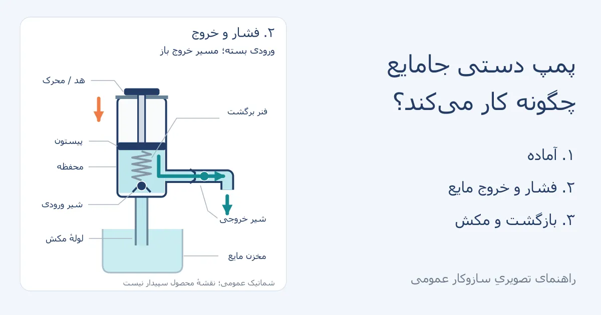
A manual liquid-soap pump works by changing the volume of a chamber and directing liquid through one-way paths. In the piston example used here, pressing the head sends liquid out; when the piston returns, the chamber refills for the next press.
What parts are inside a manual soap-dispenser pump?
This is a general schematic model of a manual piston pump, not a technical drawing of Sepidar dispensers. The path, valve type, return mechanism and installation can differ among real models. Identify the pump type before examining a particular part: sensor-operated units, foam pumps and airless systems do not necessarily use this arrangement.
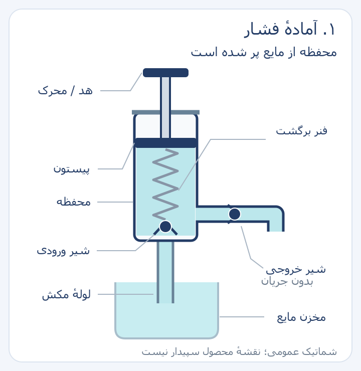
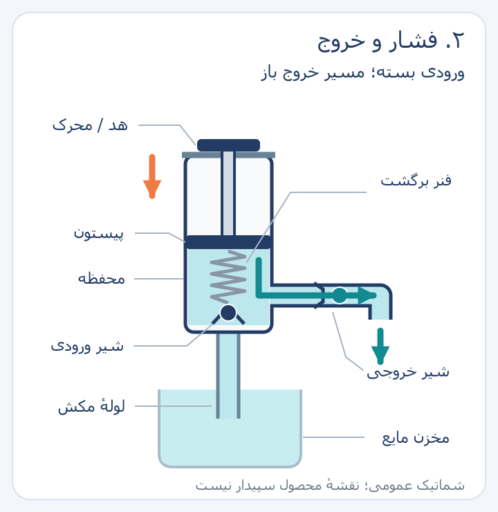
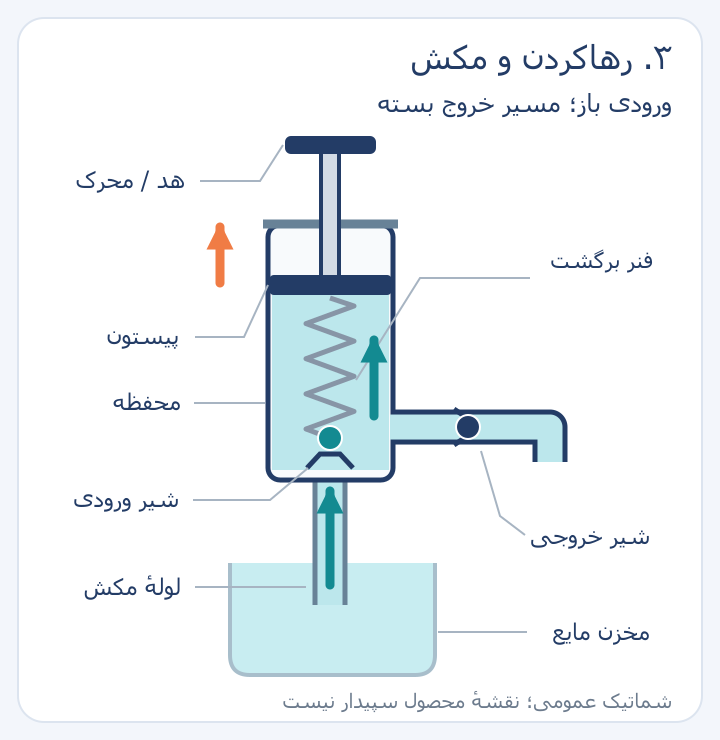
To follow the diagrams, trace the liquid from the reservoir through the tube and chamber to the outlet. The turquoise arrow shows the liquid path; the orange arrow shows actuator movement. The spring and outlet positions in this model are simplified to explain how the parts relate. Do not use the drawing as instructions for opening your dispenser.
| Part | Role |
|---|---|
| Head or actuator | Transfers hand force to the pump assembly. |
| Stem and piston | Change the effective volume of the chamber as they move. |
| Chamber | Receives and moves liquid during the pump cycle. |
| Return mechanism | Moves the actuator back to its ready position after pressure is released; in this model, it is a spring. |
| One-way valves | Control the opening and closing of the inlet and outlet paths. |
| Suction tube | Carries liquid from the reservoir to the pump inlet. |
The outer housing, container connection and seals are also part of the assembly, even if the simplified figure does not show their details. PM Plastics’ overview of pump components also explains that internal design and tube length vary with the container. Do not assume that every pump has the same number of parts or a ball valve of the same type.
How the pump cycle works: from hand pressure to refill
Click an image to view its labels at full size. The diagrams are general schematics, simplified for teaching.
| Stage | What happens in the chamber? |
|---|---|
| Ready | After priming, liquid is in the chamber for the next press. |
| Press | The chamber volume decreases and liquid moves through the outlet toward the nozzle. |
| Return | The chamber volume increases and liquid enters from the suction tube. |
1. Ready: the chamber has already filled
Consider the usual cycle after initial priming. The piston is up and the chamber contains liquid. In this teaching model, the valves prevent backflow or unintended flow at rest; the user has not yet applied force to move liquid.
2. Press: chamber volume falls and liquid exits
As the piston moves down, the space available for liquid decreases. In this model, the inlet valve stays closed so liquid does not return to the reservoir, while the outlet path opens. Liquid moves from the chamber to the outlet; the spring is compressed and stores energy for the return stage.
3. Release: the chamber refills for the next press
When hand pressure is removed, the spring in this example moves the piston back up. The chamber expands and the pressure difference opens the inlet valve, drawing liquid from the reservoir through the suction tube. The outlet path stays closed so suction does not occur from the nozzle side; the pump is ready for another cycle.
The US Department of Energy’s mechanical-science handbook, in its positive-displacement-pump section, describes inlet and outlet valves as valves that:
allow flow in only one direction.
That is, they permit flow in one direction only. This source explains a general suction-and-discharge principle; it is not a certificate, repair instruction or specification for any Sepidar model. A technical explanation from pump maker Luhang also separates initial priming from the return stage that draws liquid in. Check the information for the specific product to confirm the actual outlet and valve construction.
Why might a pump need several presses at the start?
In a new pump, after emptying, or after some cleaning methods, part of the path may contain air instead of liquid. Initial presses help move air out and bring liquid into the chamber; this is called priming. The first cycle is therefore different from the normal cycle of a filled pump.
The number of presses is not fixed for every dispenser. Follow the maker’s instructions and consider the path length and liquid. If there is still no output after the permitted steps, this article cannot diagnose a definite fault; the pump troubleshooting guide walks through symptom checks. Pressing harder is not evidence that the mechanism is understood and is not a universal fix.
Do foam, sensor-operated and airless dispensers work the same way?
These terms do not describe one shared feature: “manual or sensor-operated” describes activation; “liquid or foam” describes the output and compatible assembly; and “airless” describes a container and dispensing system. A single unit can have more than one of these characteristics.
| Type | What not to assume |
|---|---|
| Foam dispenser | Changing the soap alone turns a regular pump into a foam-producing assembly. |
| Sensor-operated | Activation by a sensor determines the liquid type or the pump’s internal design. |
| Airless | The same suction tube and reservoir arrangement must be present. |
For output selection, read the guide to foam versus regular soap dispensers. The spring’s position relative to the liquid also varies across designs. For example, the official page for a Silgan pump family describes a liquid path that does not contact metal as a feature of that family. This illustrates design variation; it is not a claim about a Sepidar product.
How can understanding the parts help you choose a pump?
The words “soap dispenser pump” alone are not enough to order a replacement. Identify the container connection, the liquid and the intended use. A clear description helps avoid assuming that any pump with a similar appearance is a suitable replacement.
| Information | Why check it? |
|---|---|
| Container and connection type | Connection fit and sealing must be confirmed for the specific assembly. |
| Liquid and use conditions | A general detergent name alone is not enough to select a pump. |
| Suction path and container dimensions | The tube must reach the liquid and fit the assembly layout. |
| Output specification and reviewable sample | Claims about output per press need data and testing on the actual model. |
The bulk viscous-liquid pump selection guide covers this step for wholesale purchasing. The teaching diagram above is not an instruction to open a sealed pump, change its spring, lubricate or replace internal parts. For those actions, use the instructions and service terms for the exact model.
Quick questions about how a soap-dispenser pump works
Does the spring pull liquid up from the reservoir? In the piston example described here, the spring helps return the piston. Liquid enters because the chamber volume changes and a pressure difference acts with the inlet path; the spring itself is not a liquid-transfer tube.
Do all pumps have a metal ball? No. Valve type, arrangement and return mechanism depend on the design. A ball shown in one schematic does not establish the material or parts used in every model.
If the head moves, is the pump definitely working? Head movement is only one observation. The liquid path, compatible parts and soap also matter; this observation alone cannot confirm that the whole pump is sound or identify a fault.